Cette page était sur le site de
HB9ABX; mais le lien ayant disparu, j'ai reproduit ici l'article
que j'avais conservé. (F5AD)
********************************
HF MOBILE
ANTENNA (HB9ABX)
Felix Meyer
update 27th May 2003 / details
July 27, 04, ... , 13.9.06
Last update =
link added
This is not the new HB9ABX HF antenna.
This antenna here was developed about 15 years
ago.
The new antenna is found under "NEW HF
ANTENNA from HB9ABX"
This mobile antenna is designed for all HF
bands from 10 to 80 meters
an proved to be very efficient in my
travels in South America on
15 and 20m for contacts to Europe and
within South America.
The antenna is my own development.
Compared to commercial HAM Antennas the
performance was
always much better, due to the larger size
and lower loss in coil.
Comparing with the Screwdriver type antennas always
resulted in 2-4 S-points
advantage in favor of this
antenna!
In field tests we compared 3
different mobile antennas, all at the same
location, at the same time, each one with 100
W power.
The 3 antennas were:
- HUSTLER mobile antenna (10
- 80 m)
- YAESU
ATAS-100
(10 - 40 m)
- HB9ABX mobile
antenna (10 - 80 m)
In all tests the signal of the home made
antenna was the strongest!
- 1 S points (up to 10 db) stronger than
HUSTLER
- 2 to 4 S points stronger than
ATAS-100/ATAS-120
These results in the ground wave (5 to
10 km), as well as in
the far field at 70 km to 1000 km distance.
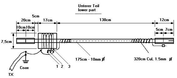
For 10, 15, and 20 m the antenna
consists of a fixed lower part and an
extensible whip (telescopic antenna of 15
to 80 cm length) on the top.
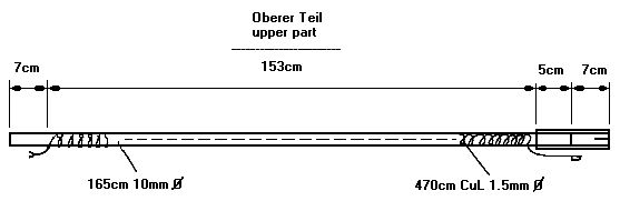
For 20, 40 and 80m a second
segment is added and at the top
follows the whip.
Both parts are made of
fiberglass rod of 10 mm diameter and 175/165 cm
length, on which a piece of enameld copper
wire (CuL) of 1.5mm diameter
is wound. Aluminium tubes are used to join
the parts together.
On both fiberglass rods equally spaced
windings of emameld copper wire of
1.5 mm dia are wound. The lower part holds
320 cm wire (79 turns) and
the upper part holds 470 cm wire (120
turns).
The loading coil is wound on a plastic
tube of 7.5cm diameter
and 17 cm length.
The same type of wire (1.5 mm CuL) is used
for the coil as for the antenna.
The coil has 33 turns in total, coil length
is 12 cm.
Seen from the bottum of the coil, there are
taps at 21, 27, and 33 turns,
which are shorted according to the
operating frequency.
Settings of the antenna in
operation:
10m : Lower part + whip + tap 3 + bridge from tap
3 to the whip
15m : Lower part + whip + tap 3
20m : Lower part + whip + tap 2
20m : Both parts + whip + tap 3
40m : Both parts + whip + tap 1
80m : Both parts + whip + no tap (full
coil)
The WARC bands 30, 17, and 12 m can be operated
by just adding
coil taps without changing the coils.
Feeding:
The antenna is fed by 50 Ohm coax (Type
RG 58)
of about 2 m length.
On the antenna side the center conductor of
the coax is connected
to the antenna wire and the coax braid is
connected to the
car chassis ground.
The antenna system requires a good
ground !
I soldered a flexible wire at both sides
inside the door frame
leading to the coax braid.
Don't forget to connect the two windings
on the fiberglass rod
together, either through the metal sleeve
between the rods,
or simply by a connector. The whip on the
top is connected to
the end of the wire below.
The desired resonance frequency is
adjusted by changing the
length of the whip on top of the antenna.
Extending the whip
lowers the frequency.
The antenna requires an antenna tuner
for operation, as
the impedance differs from 50 Ohms on
40 and 80 m.
With the aid of the tuner, the antenna is
adjusted to SWR 1.0 on all bands.
The MFJ-901B tuner is fine for this use.
It has little weight and
is very small (12.5 x 5 x 15 cm).
(Before its use it's recommended to
open it to check the adjustment of
the variable capacitors. They are
frequently bad centered, which produces
easily shorts ...)
If the transceiver and tuner are without
SWR meter then a separate
instrument is to be connected between TX
and tuner. I am using a
DAIWA CN410M which is a small cross needle
instrument best suited
for this use.
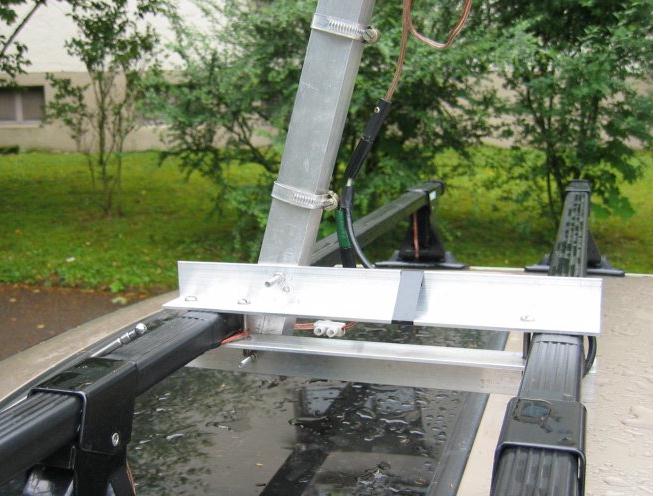
Mounting of the antenna:
I installed the antenna on top of the
car on a roof carrier.
Two aluminum angles, 30 cm length, 30mm
thigh, were fixed
with screws to the carrier and the rod
below the coil fixed to the angles
by means of two hose clamps.
Instead of the Aluminium tubes copper
tubes may be used, whatever
is found to be better. The tubes are glued
in 5 cm length over the
fiberglass rod. At the end of the 7 cm open
part of the tube, a 2 cm
long slot is sawed and a small clamp
is used to hold the inserted antenna
part .
The antenna is directed backwards at an
angle of abt. 70 degrees.
In order to prevent swinging up, the
antenna is fixed slightly down
at the end with a nylon rope. Use 2 nylon
ropes, to both sides to prevent
swinging sidewise when driving. This is
required when both antenna
elements are installed.
The top of the antenne nearly reaches
3.2 m height above ground when
both elements are in use and fixed by a
nylon.
Adjustment hints:
Initially, the antenne has te be tuned
to resonance on each band
without using the tuner.
This adjustment is done by changing the
coil tabs and then varying
the spacing between turns.
In operating mode, only the tab setting is
changed, the whip length set,
and tuned with the tuner.
Before initial adjustment, both elements have to be checked:
Before adjustment of the coil begins, the resonance of the
two elements is to be
checked and eventually adjusted. This is done with the coil in
position 3 (in short).
Measurements to be made on installed antenna and with
connected ground (= car frame),
without tuner. The resonance is measured (= minimum SWR) with
an antenna analyzer
connected at the end of the coax:
1st. Check
--------------
Only lower part + whip, coil tap 3.
Set lenght of whip to 77cm (including metal sleeve).
Resonance = 21.0 MHZ (+- 0.4 MHz)
If resonance frequ. is lower, then the number of turns is
too high.
Remove turn by turn to obtain required resonance frequency.
(I have exactly 79 turns on lower part).
2nd. Check
--------------
Perform this check after check 1 is terminated.
Both parts + whip, and coil tap 3.
Set length of whip to 25 cm (including metal sleeve).
Resonance = 14.2 MHZ (+- 0.3 MHz)
If resonance frequ. is lower, then the number of turns on
upper part is too high.
Remove turn by turn to obtain required resonance frequency.
(I have exactly 120 turns on upper part).
The initial adjustment
is done by using an antenna analyzer (e.g.MFJ-259).
Resonance is found by obtaining minimum SWR
on the instrument.
Procedure of initial adjustment : (this is done without tuner)
Lower part + whip (10 to 20 m)
- Coil tap 3 ( = all turns closed)
Adjust length of whip to obtain
min. SWR at 21.2 MHz.
Note length of whip. This is
the 15 m setting.
- Coil tap 2 (27 turns closed)
Keep length of whip from
previous setting.
Adjust spacing of the
upper 6 turns to obtain min. SWR at 14.2 MHz.
Fix coil, this is the 20
m setting.
- Coil tap 3
Make a bridge using a flexible
wire of 150 cm length with clips
between tap 3 to whip
connection (wound 2 - 3 times around rod).
Adjust length of whip to
reach min. SWR at 28.4 MHz.
Note length of whip. This is
the 10 m setting.
Both parts + whip (20 to 80 m)
- Coil tap 3
Adjust length of whip to reach min.
SWR at 14.2 MHz.
Note length of whip. This is the 20 m
setting.
- Coil tap 1
Measure SWR on 7.05 MHz and adjust spacing
of coil between
taps 1 and 2 to reach minimum SWR. Change
length of whip only,
if minimum SWR remains outside indicated
frequency.
Fix coil and note length of whip. This is
the 40 m setting.
- Coil without tap (33 turns active).
Keep length of whip and measure SWR on 3.7
MHz.
Adjust spacing of coil of the first 21 windings
to reach miminum SWR.
Change length of whip only, if min. SWR remains
outside 3.7 MHz.
Fix coil and note length of whip. This is the 80
m setting.
After terminating this adjustment the
coil winding is fixed permanently.
After this initial adjustment, the tuner is
connected to mach the SWR
exactly on operating frequency.
With my antenna the SWR without tuner on 10, 15, and 20 m
is better than 1.2 therefore tuning is only required for 40 m
and 80 m operation. This however depends from the actual
installation, especially from the ground connection.
See further details from the following drawings:
The photograph below shows the installed antenna in Chile
as CE3CWF/mobile.
(The white antenna is a 2m antenna)
Good luck in construction.
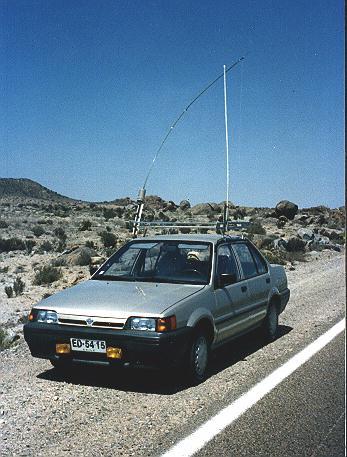 my antenna as CE3CWF
Below the mobile antenna in Switzerland as HB9ABX:
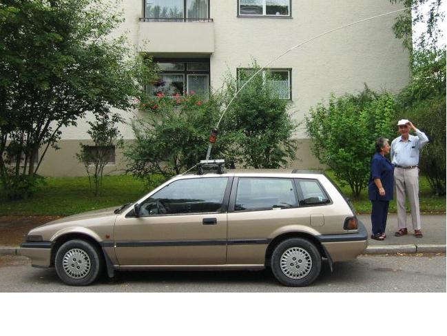
And finally the mounting of the antenna on the roof of the car:
WARNING
Working with fiberglass rods produces dangerous
dust, which easily produces allergies on the hands. Inhalation of
the dust is extremly dangerous !
Already holding the raw bars with the hand can
produce problems, therefore use protecting gloves
whenever working and handling raw fiberglass rods
and observe appropriate care when sawing.
Wash well the hands with soap after the work !
After terminating the work paint the complete rods
with a suitable lacquer to protect the surface.