Cette page
était sur le site de KC4FWC; mais le lien ayant disparu, j'ai
reproduit ici l'article que j'avais conservé. (F5AD)
********************************
Build
a FOLDED MONOPOLE antenna for 440-450 MHz CHEAP!
By Derek
McIntyre KC4FWC
If you need a unity gain 440 MHz antenna that has the basic
radiation pattern of a 1/4 wave ground plane but presents a VERY
WIDE BANDWIDTH and is DC GROUNDED for lightning protection and
eliminates wind static, then build this handy folded monopole in
30 minutes.

Tools and Parts Needed:
1. Some #12 wire (or clothes hangers) and some #14 wire (or
3/32" brass welding rods)
2. One piece of 75 ohm coax, +/- one foot, RG-11, RG-6, or RG-59
3. Piece of copper sheet about the thickness of trunkline duct
work (16 gauge)
4. 60 watt soldering iron and solder
5. SO-239 bulkhead or BNC-Female bulkhead connector
6. Ordinary hand tools
7. Watt meter (optional)
THEORY BEHIND A FOLDED MONOPOLE - Electrically to RF it presents
the same radiation pattern as a normal 1/4 wave ground plane. The
vertical pattern is approximately 30 degrees which is considered
a relatively high angle of radiation as compared to other UHF
antennas with gain, such as Celwave's Super Stationmaster
antennas with as much as 10 dB of gain with a vertical beamwidth
of 7 degrees! However, GAIN and LOW ANGLE OF RADIATION is often
not needed, and in turn can degrade repeater/base station
performance greatly in certain situations. Take into effect the
diagram below and imagine the antenna listed is a HIGH GAIN
antenna with a vertical beamwidth of 7 degrees (such as the
Stationmaster series)
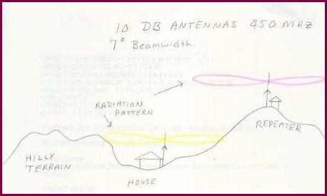
In this situation, we will say that the house is where I used to
live in Foscoe, NC in a huge hole where I am surrounded by hills
on each side. The repeater site is Beech Mountain, nearly 1500
feet above me but only 12 miles away. If I used a high gain, low
angle radiation antenna at the house, and the repeater used the
same thing, notice how our patterns miss each other. My pattern
hits the side of other hills and the repeater antenna skews
useful RF 1000 feet over my head where it doesn't do any good. If
I key the repeater and work it at all, it is probably due to
reflections off other objects.
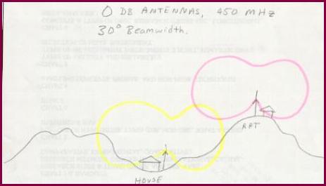
In this case, we both use a 1/4 wave ground plane antenna with a
vertical pattern of nearly 30 degrees. Though the repeater on the
mountain will not give as strong a signal out on the far horizon,
close-in performance in valleys will increase significantly as
shown above. Also, at the home station, the pattern may also hit
the other hills, but not as great a percentage. A good deal of
the RF is directed more upward and out of the hole since the
angle of radiation has now been increased.
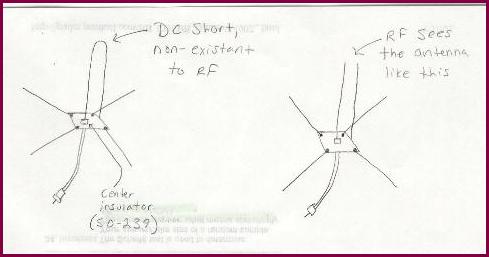
The folded monopole antenna is such as this. At an electrical 1/4
wavelength, a short back to ground is not seen as an RF short,
but a DC short. Therefore, the antenna is frequency sensitive and
will not work at harmonic multiples like a regular 1/4 wave
ground plane would. The transmitter actually sees the shorted
antenna like the picture on the right. The stub on the right side
adds capacitance to ground, lowering the resonant frequency.
Therefore, the folded monopole antenna is generally cut about 10%
shorter than a physical 1/4 wave at a given frequency to produce
the correct resonance.
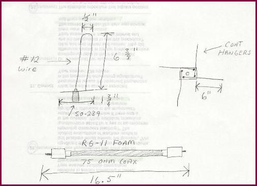
Listed above are the dimentions for the antenna. Now we are
presented with another situation when it comes to the antenna
itself. Unlike 1/4 wave ground planes which present an unbalanced
termination impedance of 50 ohms (when ground radials are bent to
a 30 degree angle), the folded monopole when constructed as such
presents a 100 ohm impedance. In order to match 100 ohms to 50,
we can use an odd quarter wavelength of 75 ohm coax as listed in
the picture. To figure this, take the impedance given times the
desired impedance (100 x 50) = 1500 and take the square root of
that number (which is 70.7) and that is the feedline matching
section you are looking for. In this case, we use 75 ohm since it
is so close. Next, to find the length, you must know the coax
velocity factor. Foam cables are usually 88% and solid dielectric
cable is around 66%. Let's use foam cable here. Now, find the
frequency you are looking for which is 445 MHz. Take 2808 and
divide by 445 and get 6.3 inches. Now, times that by the velocity
factor of 88% (0.88) and get approximately 5.5 inches. This is
ONE ELECTRICAL QUARTER WAVE LENGTH FOR 445 MHz using cable with
an 88% velocity factor. You may use this length for your matching
section, or times it by 3 and get 16.5, or times it by 7, 9, 11,
or whatever you desire so long as it is an ODD multiple. Then,
stick a barrell on the other end and run it to your 50 ohm
transmission line.
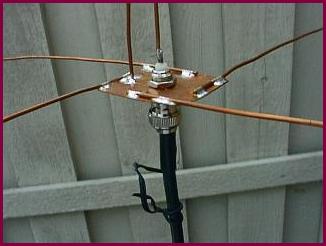
Soldering to the base and radiating element. You may choose to do
this another way by using larger conductors. When increasing the
element diameter by 2 times, increase the spacing between center
and return element by 50% to maintain proper impedance. You may
wish to connect a wattmeter or return loss bridge with tracking
generator to the antenna and check for center frequency.
Typically, at the dimentions shown there is 20 MHz of bandwidth
total below 1.5:1 VSWR. Normally VSWR at center frequency runs
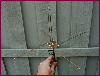
around 1.2:1. Mount the antenna by means of hose clamping the
PL-259 connector to a pipe or tie a string up and hang it froma
tree limb. Again, this antenna was built in around 15 minutes on
a lunch break at work, using primitive tools and materials. One
could build an extremely strong version of this, like Decibel
Products DB-201.
Retour au menu
antennes