Cette page était sur le site de
KG4OKM; mais le lien ayant disparu, j'ai reproduit ici l'article
que j'avais conservé. (F5AD)
********************************
The zeppelin antenna: (
or sometimes referred to as a zep )
A end fed antenna used on the big zeppelin airships
(thus the name ZEPPELIN antenna) of the 1930's where the wire
trailed behind the dirigible.
The wires 1 and 2 were on reels and could be played out for
the band wave length ( frequency ) desired and matching of the
equipment for communications.
For a 1/2 wave length zeppelin antenna wire 1 is app. 3/4
wave length and wire 2 is app. 1/4 wave length, each was adjusted
for the best loading of the transmitter. The first 1/4 wave
length from the feed point forms a parallel transmission line and
does not radiate. The remaining 1/2 wave length of wire is the
radiating part of the antenna.
Below is a 3.75 wave length (3.5 wave length antenna) example
for six meters. If it looks like a "J" pole laying on
its side there is good reason, the " J " pole antenna
is just one of the variations of the zeppelin antenna around, not
to mention a lot of dipole and other antennas that have been
mis-named as zep antennas.
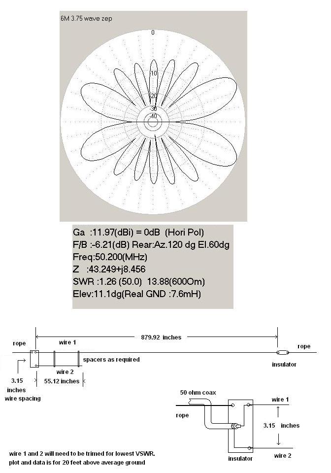
WIRE USED FOR MODEL IS #14 AWG COPPER
If you use any other size or type of wire the DIMENSIONS WILL
CHANGE.
Note: The spacing between the wires #1 and #2 should not
be changed! If you do the match will not be 50 ohms at feed
point.
The spacing is critical for transforming the high impedance
(app. 4 to 5K ohms for a 1/2 wave end fed antenna) to the
50 ohm feed point.
How to tune the antenna:
(1) Put the antenna up in the clear about head high, adjust the
long wire length for the lowest vswr at the center frequency you
designed it for, you are looking for the lowest vswr you can get,
not necessarily the best.
(2) Adjust the short wire length for the lowest vswr, should be
1.5:1 or less.
(3) Hoist antenna to operating position and have fun.