Cette page était sur le site de W0LMD;
mais le lien ayant disparu, j'ai reproduit ici l'article que
j'avais conservé. (F5AD)
Making a Circularly Polarized 2401 MHz Patch
Feed
 My W0LMD patch
version has the usual 2 metal plates. The reflector backplate
is a 4" in diameter piece of 1/16" aluminum. A
1/8" hole is drilled in the center, and 11/16" out from
the center is a 3/8" hole through which the center conductor
of a type N connector extends. Most of the time I use a female
type N chassis connector but sometimes I use a male type N
connector for directly attaching the patch to the input of a
downconverter. The type N connector, on the side of the reflector
away from the patch, is attached to the reflector plate by four
pan head 4-40 bolts with the heads on the side of the reflector
facing the patch plate. The connector is slightly skewed
clockwise, about 30 degrees, when looking at the type N connector
from the patch side of the reflector, which provides better
clearance for the tuning screw on the patch.
My W0LMD patch
version has the usual 2 metal plates. The reflector backplate
is a 4" in diameter piece of 1/16" aluminum. A
1/8" hole is drilled in the center, and 11/16" out from
the center is a 3/8" hole through which the center conductor
of a type N connector extends. Most of the time I use a female
type N chassis connector but sometimes I use a male type N
connector for directly attaching the patch to the input of a
downconverter. The type N connector, on the side of the reflector
away from the patch, is attached to the reflector plate by four
pan head 4-40 bolts with the heads on the side of the reflector
facing the patch plate. The connector is slightly skewed
clockwise, about 30 degrees, when looking at the type N connector
from the patch side of the reflector, which provides better
clearance for the tuning screw on the patch.
The new patch plate was smaller, 2
3/8" in diameter, than my non circular 2401 MHz patches
and was made from some hardware or hobby store 1/16" thick
brass plate. I drilled three 1/8" holes in this patch plate.
The first hole was in the center of the patch plate, the second
hole was 11/16" out from the center (mates to the type N
center conductor on the reflector), and a third hole is 1/2"
clockwise from the type N hole, also 11/16" out from the
center hole. I then carefully tapped this 3rd hole with a 6-32
tap.
I put a 1/2" long pan head 4-40 bolt through
the center hole of the reflector from the side away from the
patch, and fastened the center bolt to the reflector with two
1/4" size 4-40 nuts. This provides the patch spacing, which
is about 3/16". You can trial fit the patch to the
reflector, verifying that the second hole in the patch plate just
fits over the center conductor of the type N connector. The third
hole, tapped to 6-32, should be clockwise from the 2nd hole for
LHCP. If counterclockwise (anti-clockwise for you Brits) from the
2nd hole, the patch becomes RHCP. Since the dish reflection
inverts polarity, the desired RHCP dish needs the clockwise LHCP
location for the third hole.
Now carefully screw a 1/2" long flat head
6-32 bolt into the threaded third hole on the patch, from the
side of the patch that will be facing the reflector. Leave the
head about 1/8" above the patch surface for now. Attach a
1/4" 6-32 nut on the other side of this tuning bolt to act
as a tuning lock. Finger tighten only as this 6-32 flat head bolt
is riding on a single thread. If you strip the threads in the
brass patch plate you can always solder the lock nut to the
plate. But be careful.
Fasten the patch to the center bolt with another
4-40 nut, and solder the Type N center conductor to the 2nd hole
in the patch. I experimentally determined that the best signal
from this patch feed resulted when the flat head of the 6-32 bolt
was spaced .020", the thickness of three postcards (direct
mail "Bingo cards") from the surface of the reflector.
Lightly snug up the tuning lock nut when this spacing is
achieved. Later, if you are happy with the performance, you can
seal the nuts with some fingernail polish.
Two small disks, a type N connector, 6 bolts and
8 nuts later, I had a really good performing 2401 MHz patch feed
for my big center fed dishes. It takes me about 1/2 hour, tops,
to make this great patch feed. When the squint angle is high
(AO-40's transmitting and receiving antennae aren't pointing my
way), this feed will produce a strong uniform signal with much
less QSB compared to a linear feed.
Show an' Tell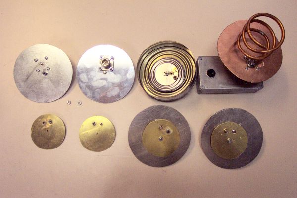
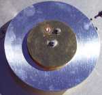
The disk in the upper left is a 4" reflector
showing the side that faces the patch. The pan head 4-40 bolt
heads are on this side and the center 4-40 bolt is facing upwards
with two 1/4" 4-40 nuts providing the 3/16" reflector
to patch spacing holding it to the plate. The reflector plate to
its right is the outside view of the reflector with a type N
female connector attached to this side.
The 2401 MHz patch disk at the bottom left shows
the side of a patch disk that faces away from the reflector.
Notice the hole in the center, a hole at the upper left that
mates with the center conductor of the type N connector in the
reflector and the clockwise third hole that was tapped 6-32 has
the threaded end of a 1/2" long flat head 6-32 bolt with an
attached 1/4" 6-32 nut. The patch to its right is the flip
side which will face towards the reflector, with the center hole
at the bottom, the type N center conductor hole now at the right
when flipped, and the 6-32 threaded hole has the 1/2" long
6-32 flat headed bolt and locking nut with the threads facing
upwards. The 2401 MHz patch plate to its right is the flip side
that faces the reflector, showing the shiny flat head of the
1/2" long 6-32 flat head bolt.
The 2 disks at the bottom right are finished 2401
MHz circular patches, a normal LHCP one and the one at the bottom
right has the tuning screw at counter-clockwise for RHCP. If
truly circular, it should have a definitely weaker signal when
attached as feed for a dish receiving a RHCP signal. It does show
about a 10 db weaker signal.
The 2401 MHz patch feed to left of the helix is
my "Safeway Special", which has a 4" peach can cut
to 1" high side ring reflector and a Campbell's soup can lid
cut down to 2 3/8" with LHCP polarization. This patch feed
is slightly weaker than the patch below it due to under
illumination, but would be good feed if you are experiencing off
axis QRM from 2400 MHz devices.
In the upper right is my 2400 MHz test signal
generator. It has a 50 MHz TTL crystal oscillator (available 3
for $1 from Electronic Goldmine (800) 445-0697 -$10 minimum order
(That's a lotta xtals!) - they have other junque listed at
http://www.goldmine-elec.com - or put a 50 MHz TTL crystal
oscillator, p/n 76831, from Jameco (800)-831-4242 for $2 - no min
order) inside the die cast box along with a 4.8v NiCad
rechargeable battery. 50 MHz is handy as the downconverter picks
up the harmonics, but the 2M xcvr doesn't. The 3 turn RHCP helix
is tied directly to the output pin of the TTL oscillator, heat
sinked to the top of the die cast box. The wider angle RHCP patch
at the bottom right can also be attached to the signal source. It
puts out a weaker signal over a wider beam pattern .I have
another similar test signal generator that uses a 16 MHz TTL
crystal oscillator, Jameco p/n 27908. I made 1/4 wave verticals
for 145 MHz, 435 MHz and 1296 MHz for testing antennas on these
bands. I also use a Gardiner 2400 MHz signal source with a linear
dipole & reflector output, available from K5GNA, mentioned
elsewhere  as an AIDC
downconverter source, for $35. This puts out a very strong signal
on a 9.6 volt rechargeable NiCad battery that should not change
in received signal level when rotated if the dish & feed are
really performing in circular mode.
as an AIDC
downconverter source, for $35. This puts out a very strong signal
on a 9.6 volt rechargeable NiCad battery that should not change
in received signal level when rotated if the dish & feed are
really performing in circular mode.
I made the 2401 MHz patch feed, shown at the
left, that had a reflector the same size as the C band Chaparral
feed that had been on the TVRO dish. The bolt hole spacing (4
1/8" square) was the same, so it was a simple unbolt and
replace operation.
A single band patch antenna for 2401 MHz can be
made with a 6 3/4" shiny aluminum disk, a 2 3/8" soup
can lid (or get fancy and obtain some 1/16" brass sheeting @
ACE hardware), and a type N, male or female, connector. I make
this circular polarized by capacity loading it out of phase. I
concentrate on fully utilizing the dish, netting a few extra db
from a higher efficiency dish. Making it really circular
polarized gains 3 db which is equivalent to doubling the surface
area of your dish and results in less QSB under marginal
conditions.
Retour au menu
antennes