Le lien vers cet article de ON1AIJ ayant disparu, j'ai reproduit ici l'article que j'avais conservé. (F5AD)
Explanation
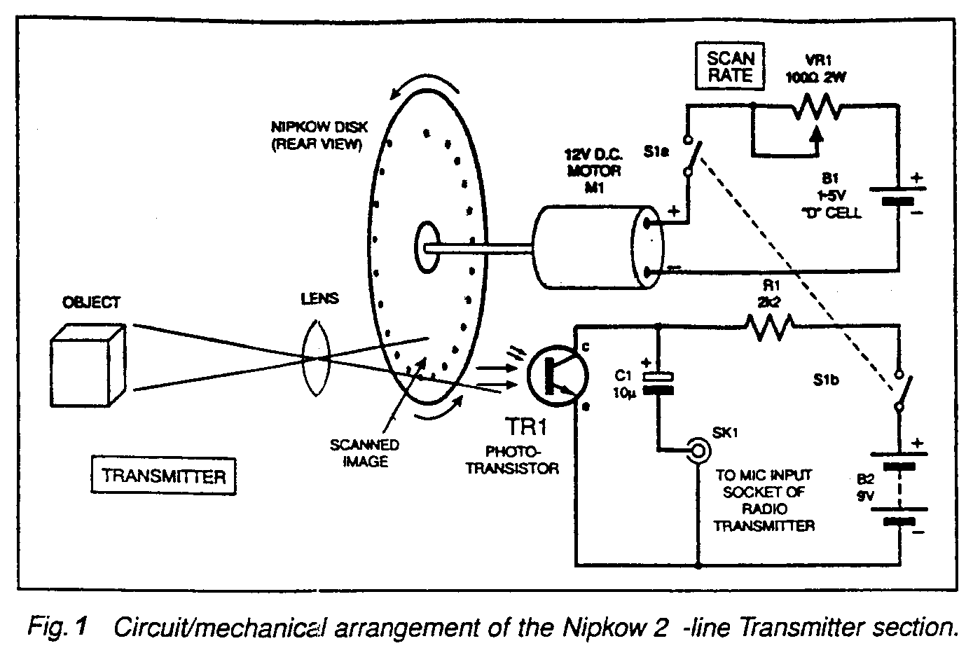
The system show in Fig 1 illustrates a simple but facinating electromechanical technique for transmitting a small image over amateur radio bands. It consists of a simple modulator based on a Nipkow-disc , a mechanical scanning device used in early television systems. The Nipkow disc has a single-revolution spiral of small holes ( 24 in this case ) which if rotated can be used to provide raster scanning of an object. With the circuit shown , a basic 24-line monochrome video image may be sent using amateur radio equipement over a good quality clear voice channel. This resolution is high enough for facial recognition of a person in close-up. It should not be compared to a slow-scan system which can only send still images. Readers may also wish to experiment with other transmission media ( e.g. wirebased audio, intercoms etc. )

Transmitting
The transmitter section, which also shows the relative placement of the mechanical parts, is shown in Fig 1. A Nipkow disc may be made from stiff card, using a plate to draw a circle 180 mm diameter or so ( you can also use CD's or LP's ) The opject to be pictured must be brighly lit, and it is captured through a lens and converted into a narrow-band vision waveform by TR1, a phototransistor placed in a plastic box behind the scanning disc. The phototransistor ( e.g. a PN202, but other types may works equally well ) requires a 9V supply. A good-quality d.c. motor ( say, 12V d.c. ) is powered from a single D-cell and potentiometer VR1 ( rated at 2W ) controls its speed. The signal is decoupled by capacitor C1 and applied to the microphone input socket SK1 of the radio transmitter.

Receiver
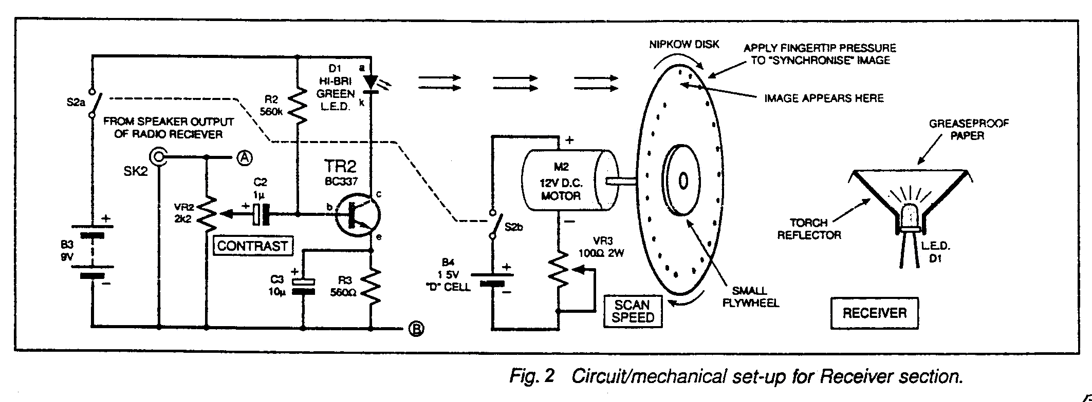
In Fig 2 the loudspeaker/headphone output is fed to a single transistor stage consisting of TR2 and surrounding components. The Led D1 is a high-brightness green device placed in a flashlight reflector, and a piece of greaseproof or tracing paper is placed over it to obtain a more uniform spread of light. With this placed underneath the receiver disc, a reasonably uniform raster is obtained. Note that the picture requires the room to be in near darkness if it is to be discemible by looking through the spinning disc.The receiver-disc is rotated slightly faster than the transmitter-disc and the image will then be visible, although it may be rolling or swirling. By applying very light pressure to the receiver-disc, it can be synchronised to the point where you can get a reasonably stable image. A flywheel, formed from an old loudspeaker magnet, was placed on top of the prototype receiver-disc to add some momentum and help with synchronisation. None of the parts are critical and substitutes may be made. An experimental but worthwhile modification to the receiver is shown in Fig 3 which offers a form of sync. control.
This provides some pulse advancement on the receiver-disc rotation which is now controlled by a transistor Darlington pair TR3 and TR4. It is important that a good quality smooth d.c. motor is used, and the two motors should have reasonably matched characteristics. Although the circuit is not perfect, it is well worth the extra effort.